My heating element in soldering station WEP 968DB+ finally fail.
I got replacement and go for this simple repair.
1)
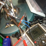
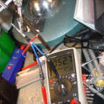
First is check if heating element is failed (check resistance between red leads from heater – my read infinity what’s mean fail open).
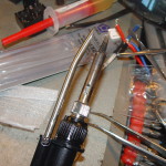
2) Mount new heating element
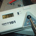
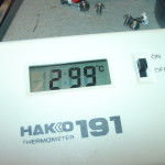
3) When i first run soldering station displayed temperature was 300*C and real temperature was almost 400*C so i need to calibrate it.
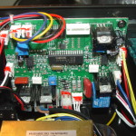
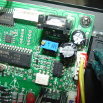
I was thinking it’s a MCU controlled station so i tried pushing + – temperature buttons, powering on / off while pressing buttons but i was unable to enter calibration from front panel… after opening i found that calibration is done by multi turn potentiometer…
Calibration pot is blue one, close to soldering iron switch (and side) opposite will be probably or hotair heater.
Tips while calibration:
– Avoid cleaning / apply lot solder just before measurement – when You do this You lower temperature of tip and station will send more power to make constant temperature and You will get higher temperature that will drop in seconds giving false positive high.
– Avoid testing just before plugging in – it send more power while starting and temperature will be false high – will drop later
– Try to calibrate as close to Your working point temperature (if You work at 315*C calibrate to 315*C) not for 200*C. The fare You will go from calibrated temp there will be more difference!
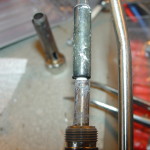
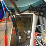
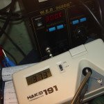
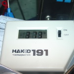
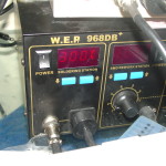
Here are some pictures from job.

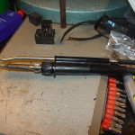
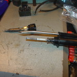
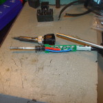
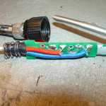
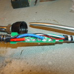
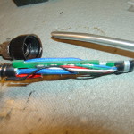
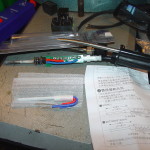
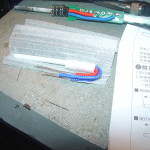
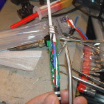
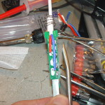
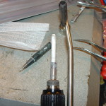
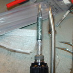
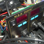
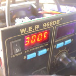
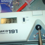
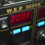
This is very practical stuff. Thank you very much for sharing all these details.
thank you for your repair information. Where did you get the replacement element and what was the part number
THank you for your troubleshooting information. Where did you get the spare element and what was the part number?
I use this one:
http://www.ebay.com/itm/White-Heating-Element-for-HAKKO-Soldering-Station-Iron-A1321-936-937-907-913-/172106025558?hash=item2812518a56:g:XDwAAOSwll1WxWy~
Make sure to buy one with 4 leads (2 for heating element, 2 for temp sensor).
Regards
Thanks for posting the insides of your 968DB+ machine and showing how to calibrate. I’m having a problem with mine as the secondary on the transformer over heated shorted out. When I opened mine I saw a solder blob on R37 at the top and wondered if something had blown. I came across a website where a guy showed the inside of his brand new machine and it had the same solder blob thing. I noticed you R37 had a zero value so at least the solder bridge instead of smd resistor seems intentional from manufacture. I have a couple of questions if you don’t mind.Does the hot air have a steady continuous stream or is there a pulsate puffing feel. And is that thermal paste on the threads of your soldering iron hold down nut?
Thank You for comment,
Air flow is steady in my opinion (there is a very very tiny pulsating due to diaphragm pump but i don’t think You are talking about it) – If You wish You can record video of ball inside i will compare against mine.
Yes this is a thermal paste, that was a my experiment (failed) to get better heat dissipation between tip and heater. Thermal paste went to solid at 400*C and it was a major failure leading me to clean heater and tip.
In future im planing to try some copper based paste that is allowed for high temp and should stay liquid.
In my imagination, having paste there will get faster response when You touch tip to solder joint and pull heat (temperature is measured at heating element) so there is time delay, but i just ended up cranking up temperature and now im solder at 315 not having any problems 🙂